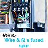
Wiring and fitting the fused spur on indoor home air conditioning systems.
The video attached shows how to fit a 13amp fused spur with the interconnecting ac feed cable, condensate pump power and over flow contacts. The interconnecting cable of a split Home Air Conditioning Systems will be a four core cable that is 1.5mm and outdoor weather-proof. In the U.K., the core cables will carry mains power 240v Live, Neutral and also Earth.
The additional third cable is required for the communications between the indoor and outdoor unit. However, this will be a low voltage feed between 10-30v depending on the manufacturer. The low voltage feed will be need to be permanently linked in side the switch with a connector. This could be a connector block, a Wago , crimp to name a few
Identifying your voltage feeds
Read the manufacturers wiring diagram and identify what terminals on your outdoor unit. Carry the Live and Neutral feed into your indoor unit. The terminals will be numbered 1,2,3 and earth on the outdoor unit. On Daikin , Mitsubishi Electric and Hitachi room air conditioning, number 1 is typically the main Live, 2 the neutral and 3 the comms. There are domestic air conditioning units that take their power supply directly to the indoor units with a manufacturer pre installed supply cable. In this event, your interconnecting cable will only carry low voltage communications between the outdoor and indoor unit. Therefore, this cable will not need to be ran through any fused spur switch. The main power supply cable coming out of the indoor unit will need to be connected to the spur switch. The cable wires will connect to the Live and Neutral “in" or “supply" terminals Power supply feeds to the indoor unit are usually found with commercial air conditioning VRV and VRF systems. These will require an internal ring mains supply which should be handled by a qualified electrician and air conditioning installation contractor.
Fitting the Spur
Fix the fuse spur back box tight beside the indoor unit, to the left or right of the unit. Do not fit the spur underneath the unit in the event of a future water leak it is an electrical fire hazard. Prepare the back box ready for the incoming cables by tapping out the internal knock outs. The interconnecting ac cable needs to be lopped and cut into to cables and fitted in the back. Feed in the condensate pump power cable also at this point. Screw the back box into the wall surface once you have all the cables pulled in and its positioned flush against the unit. The switch itself maybe be a little wider than the back box, so check this as you may need to leave a small 1mm gap between the unit and back box. If you don’t then you will find the switch will not align with the back box when you are screwing it down.
Wiring into the switch
On the back of the switch you will be find the wiring indications as follows:
- “L IN" (Live in) and “N IN" (Neutral in) – this is your incoming supply cable
- “L OUT" (Live out) and “N OUT" (Neutral out) – this is your supply to the indoor unit and the condensate pump.
Another switch maybe have the below indicators for the same meaning as above:
- Supply L and Supply Neutral – this is your incoming supply cable
- Load L and Load Neutral – this is your supply to the indoor unit and the condensate pump.
Fit all the cables into the respective terminals. Additionally, remember your load side. “LIVE & NEUTRAL OUT/LOAD" will have both the indoor unit and condensate pump cables, two in each terminal, feeding out.
Over flow contacts
The condensate pump will also have two or three additional auxiliary wires. Use these to cut out the unit in the event of a pump failure. The comms wires, number 3, will be the only two cables from your interconnecting cable that are not going into the fuse spur switch terminals. These two wires need to be connected to either end of the over flow contact wires. Connect these remaining two comms wires to the black two wire overflow contact fees from the pump, also in the switch, using a connector. In a three wire over flow contact cable situation you wire the incoming comms wire to the over flow wire marked “common". The other comms wire you wire to the “N/C" (normally closed) marked wire. When the float magnet in the reservoir rises to it’s highest position, the contacts will break. Therefore, this will break the interconnecting comms wire and send the unit into a fault. The pump therefore, will be the first place to check if your Home Air Conditioning Systems unit shows a comms error alarm.
Watch the video for a full how to guide on all of the above.
The guide is based on UK wiring, electrical voltage and manufacturers. Additionally, It applies to training professionals and people with trade experience. However, if you are having problems, contact us directly for help with your Home Air Conditioning Systems.

